- 您現在的位置:買賣IC網 > PDF目錄373920 > AD7854ARS (ANALOG DEVICES INC) 3 V to 5 V Single Supply, 200 kSPS 12-Bit Sampling ADCs PDF資料下載
參數資料
| 型號: | AD7854ARS |
| 廠商: | ANALOG DEVICES INC |
| 元件分類: | ADC |
| 英文描述: | 3 V to 5 V Single Supply, 200 kSPS 12-Bit Sampling ADCs |
| 中文描述: | 1-CH 12-BIT SUCCESSIVE APPROXIMATION ADC, PARALLEL ACCESS, PDSO28 |
| 封裝: | SSOP-28 |
| 文件頁數: | 10/28頁 |
| 文件大小: | 264K |
| 代理商: | AD7854ARS |
第1頁第2頁第3頁第4頁第5頁第6頁第7頁第8頁第9頁當前第10頁第11頁第12頁第13頁第14頁第15頁第16頁第17頁第18頁第19頁第20頁第21頁第22頁第23頁第24頁第25頁第26頁第27頁第28頁
AD7854/AD7854L
–
10
–
REV. B
STATUS REGISTER
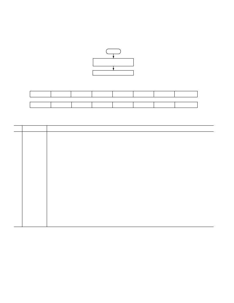
The arrangement of the status register is shown below. The status register is a read-only register and contains 16 bits of data. The
status register is selected by writing to the control register and putting two 1s in RDSLT1 and RDSLT0. The function of the bits in
the status register are described below. The power-up status of all bits is 0.
START
READ STATUS REGISTER
WRITE TO CONTROL REGISTER
SETTING RDSLT0 = RDSLT1 = 1
Figure 4. Flowchart for Reading the Status Register
MSB
ZERO
ZERO
ZERO
ZERO
ZERO
ZERO
PMGT1
PMGT0
ONE
ONE
AMODE
BUSY
CALMD
CALSLT1
CALSLT0
STCAL
LSB
Status Register Bit Function Description
Bit
Mnemonic
Comment
15
14
13
12
11
10
9
8
7
6
5
ZERO
ZERO
ZERO
ZERO
ZERO
ZERO
PMGT1
PMGT0
ONE
ONE
AMODE
These six bits are always 0.
Power Management Bits. These bits will indicate if the part is in a power-down mode or not. See Table VI
in Power-Down Section for description.
Both these bits are always 1.
Analog Mode Bit. When this bit is a 0, the device is set up for the unipolar analog input range. When this
bit is a 1, the device is set up for the bipolar analog input range.
Conversion/Calibration Busy Bit. When this bit is 1, this indicates that there is a conversion or calibration
in progress. When this bit is 0, there is no conversion or calibration in progress.
Calibration Mode Bit. A 0 in this bit indicates a self-calibration is selected, and a 1 in this bit indicates a
system calibration is selected (see Table III).
Calibration Selection Bits and Start Calibration Bit. The STCAL bit is read as a 1 if a calibration is in
progress and as a 0 if there is no calibration in progress. The CALSLT1 and CALSLT0 bits indicate
which of the calibration registers are addressed for reading and writing (see section on the Calibration
Registers for more details).
4
BUSY
3
CALMD
2
1
0
CALSLT1
CALSLT0
STCAL
發布緊急采購,3分鐘左右您將得到回復。