- 您現在的位置:買賣IC網 > PDF目錄375865 > FN (TT Electronics / Welwyn) Fusible Nickel Film Resistors PDF資料下載
參數資料
| 型號: | FN |
| 廠商: | TT Electronics / Welwyn |
| 英文描述: | Fusible Nickel Film Resistors |
| 中文描述: | 熔鎳膜電阻 |
| 文件頁數: | 1/2頁 |
| 文件大小: | 133K |
| 代理商: | FN |
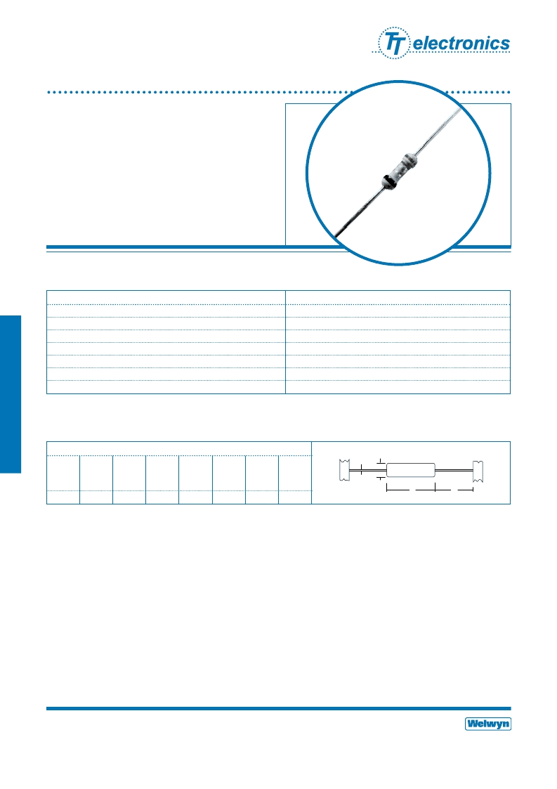
Fusible Nickel
Film Resistors
FN Series
Predictable fusing characteristics
Constant current fusing
Flameproof
FN4
Power rating at 70°C
watts
0.4
Resistance range
ohms
0R1 to 20R
TCR
ppm/°C
See Figure 1
Resistance tolerance*
%
5, 10, 20
Standard values
E24 preferred
Thermal impedance
°C/watt
215
Ambient temperature range
°C
-55 to 155
General Note
Welwyn Components reserves the right to make changes in product specification without notice or liability.
All information is subject to Welwyn’s own data and is considered accurate at time of going to print.
Welwyn Components Limited
· Bedlington, Northumberland NE22 7AA, UK
Telephone: +44 (0) 1670 822181 · Facsimile: +44 (0) 1670 829465 · Email: info@welwyn-tt.com · Website: www.welwyn-tt.com
* Below 1R, 10 and 20% only.
Electrical Data
Issue B · 03.02
A subsidiary of
TT electronics plc
Welwyn Components
168
Construction
The nickel film is deposited on a high purity ceramic rod. End
caps are force fitted and termination wires welded to the
caps. The resistive film is adjusted to the required value by a
helical cut; finally the flame retardant lacquer protection is
applied to the resistor body and the resistor is marked with an
indelible ink.
Terminations
Material
Solder-coated copper wire.
Strength
The terminations meet the requirements of
IEC 68.2.21
Solderability
The terminations meet the requirements of
IEC 115-1, Clause 4.17.3.2
Marking
Resistors are colour coded with five bands. Four of the bands
are used to indicate value and tolerance, with IEC 62 colours
being used. A fifth black band denotes constant current
fusibility.
Solvent Resistance
The body protection and marking are resistant to all normal
industrial cleaning solvents suitable for printed circuits.
Flammability
The resistors will not burn or emit encandescent particles
under any condition of applied temperature or power
overload.
Dimensions (mm) & Weight (g)
PCB
Min.
bend
radius
mounting
centres
Wt.
nom
Type
L Max
D Max
f min
d nom
FN4
6.2
2.5
21.0
0.6
10.2
0.6
0.3
Physical Data
L
D
f
d
相關PDF資料 |
PDF描述 |
|---|---|
| FOD050L | HIGH SPEED TRANSISTOR OPTOCOUPLERS |
| FOD250L | HIGH SPEED TRANSISTOR OPTOCOUPLERS |
| FOD053L | HIGH SPEED TRANSISTOR OPTOCOUPLERS |
| FOD060L | SSR OCMOS FET 200MA NO 6-DIP |
| FOD260L | LVTTL/LVCMOS 3.3V High Speed-10 MBit/s Logic Gate Optocouplers |
相關代理商/技術參數 |
參數描述 |
|---|---|
| FN 1393-2.5/05-11 | 制造商:Schaffner 功能描述:Power Entry Module Filtered M 3 POS 250VAC 2.5A Switch/Fuse ST 1 Port |
| FN 2010-1/06 | 制造商:Schaffner 功能描述:FILTER FN 2010-1/06 |
| FN 2010-16/06 | 制造商:Schaffner 功能描述:Power Line Filter 0Hz to 400Hz 16A 250VAC Quick Connect Chassis Mount 制造商:Schaffner 功能描述:Power Line Filter 0Hz to 400Hz 16A 250VAC Quick Connect Flange Mount |
| FN 2010-20/08 | 制造商:Schaffner 功能描述:Power Line Filter 0Hz to 400Hz 20A 250VAC Threaded Stud Chassis Mount |
| FN 2020-10/06 | 制造商:Schaffner 功能描述:Power Line Filter 0Hz to 400Hz 10A 250VAC Quick Connect Chassis Mount |
發布緊急采購,3分鐘左右您將得到回復。