- 您現在的位置:買賣IC網 > PDF目錄382301 > MC4GH01GNMCA-2SA00 (SAMSUNG SEMICONDUCTOR CO. LTD.) SAMSUNG MultiMediaCard PDF資料下載
參數資料
| 型號: | MC4GH01GNMCA-2SA00 |
| 廠商: | SAMSUNG SEMICONDUCTOR CO. LTD. |
| 英文描述: | SAMSUNG MultiMediaCard |
| 中文描述: | 三星多媒體 |
| 文件頁數: | 72/102頁 |
| 文件大小: | 1384K |
| 代理商: | MC4GH01GNMCA-2SA00 |
第1頁第2頁第3頁第4頁第5頁第6頁第7頁第8頁第9頁第10頁第11頁第12頁第13頁第14頁第15頁第16頁第17頁第18頁第19頁第20頁第21頁第22頁第23頁第24頁第25頁第26頁第27頁第28頁第29頁第30頁第31頁第32頁第33頁第34頁第35頁第36頁第37頁第38頁第39頁第40頁第41頁第42頁第43頁第44頁第45頁第46頁第47頁第48頁第49頁第50頁第51頁第52頁第53頁第54頁第55頁第56頁第57頁第58頁第59頁第60頁第61頁第62頁第63頁第64頁第65頁第66頁第67頁第68頁第69頁第70頁第71頁當前第72頁第73頁第74頁第75頁第76頁第77頁第78頁第79頁第80頁第81頁第82頁第83頁第84頁第85頁第86頁第87頁第88頁第89頁第90頁第91頁第92頁第93頁第94頁第95頁第96頁第97頁第98頁第99頁第100頁第101頁第102頁
MultiMediaCard
TM
72
Sep.22.2005
Revision 0.3
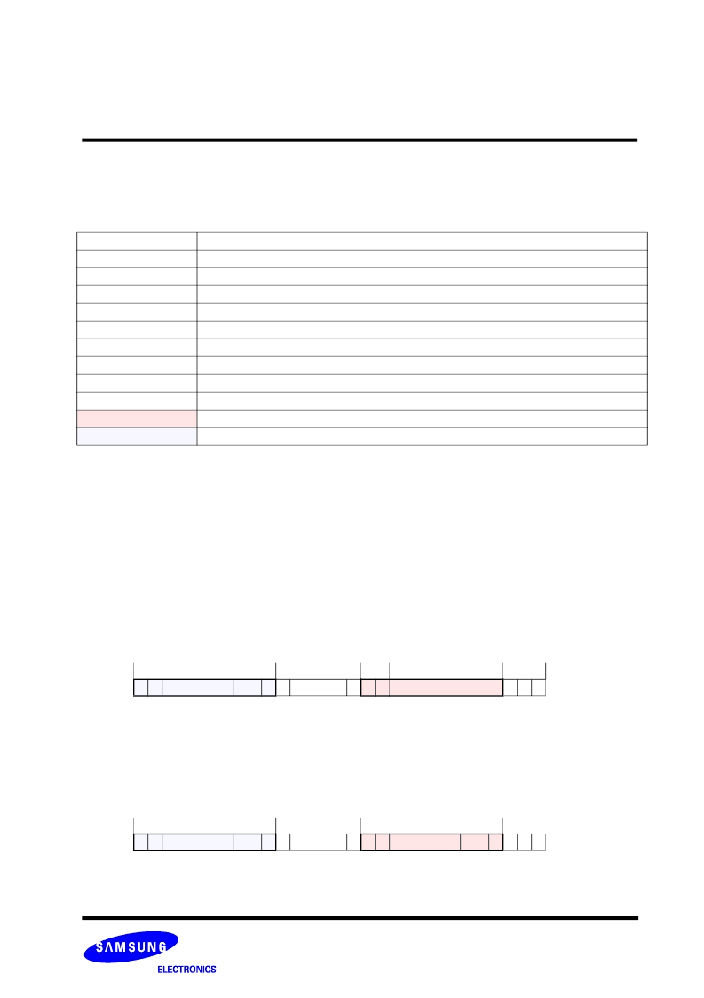
6.12 Timing Diagrams
All timing diagrams use the following schematics and abbreviations:
The difference between the P-bit and Z-bit is that a P-bit is actively driven to HIGH by the card respectively host output
driver, while Z-bit is driven to (respectively kept) HIGH by the pull-up resistors R
CMD
respectively R
DAT
. Actively-driven P-
bits are less sensitive to noise.
All timing values are defined in Table 6-25.
6.12.1 Command and Response
Both host command and card response are clocked out with the rising edge of the host clock.
Card identification and card operation conditions timing
The card identification (CMD2) and card operation conditions (CMD1) timing are processed in the open-drain mode. The
card response to the host command starts after exactly N
ID
clock cycles.
Figure 6-7 : Identification Timing (Card Identification Mode)
Assign a card relative address
The SET_RCA (CMD 3) is also processed in the open-drain mode. The minimum delay between the host command and
card response is N
CR
clock cycles.
Figure 6-8 : SET_RCA Timing (Card Identification Mode)
Symbol
Definition
S
Start bit (= ‘0’)
T
Transmitter bit (Host = ‘1’, Card = ‘0’)
P
One-cycle pull-up (= ‘1’)
E
End bit (=’1’)
Z
High impedance state (-> = ‘1’)
X
Driven value, ‘1’ or ‘0’
D
Data bits
*
Repetition
CRC
Cyclic redundancy check bits (7 bits)
Card active
Host active
Table 6-24 : Timing Diagram Symbols
←
Host Command
→ ←
N
ID
cycles
→
S T
content
CRC E Z
←
CID or OCR
→
content
CMD
* * *
Z S T
Z Z Z
←
Host Command
→
←
N
CR
cycles
→
←
S T
content
CRC E Z
Response
content
→
CRC E Z Z Z
CMD
* * *
Z S T
相關PDF資料 |
PDF描述 |
|---|---|
| MC4GH02GNMCA-2SA00 | SAMSUNG MultiMediaCard |
| MC206 | THIN SMD LOW/MEDIUM-FREQUENCY CRYSTAL UNIT |
| MC2300 | Navigator Motion Processor |
| MC26LS30 | Dual Differential Quad Single-Ended (EIA-423-A) Line Drivers |
| MC26LS30D | CABLE GLAND, PG29 |
相關代理商/技術參數 |
參數描述 |
|---|---|
| MC4GH02GNMCA-2SA00 | 制造商:SAMSUNG 制造商全稱:Samsung semiconductor 功能描述:SAMSUNG MultiMediaCard |
| MC4M | 制造商:G & J HALL 功能描述:STEP DRILL MULTICUT 4-12MM X 2MM 制造商:G & J HALL 功能描述:STEP DRILL, MULTICUT, 4-12MM X 2MM |
| MC-4-MALE | 制造商:Multi-Contact USA 功能描述: |
| MC4MANUAL | 制造商:Omron Corporation 功能描述: |
| MC-4R128CEE6B | 制造商:NEC 制造商全稱:NEC 功能描述:Direct Rambus DRAM RIMM Module 128M-BYTE 64M-WORD x 16-BIT |
發布緊急采購,3分鐘左右您將得到回復。