- 您現在的位置:買賣IC網 > PDF目錄371063 > MC74HC162A (Motorola, Inc.) Presettable Counters PDF資料下載
參數資料
| 型號: | MC74HC162A |
| 廠商: | Motorola, Inc. |
| 元件分類: | 通用總線功能 |
| 英文描述: | Presettable Counters |
| 中文描述: | 可預置計數器 |
| 文件頁數: | 4/14頁 |
| 文件大小: | 323K |
| 代理商: | MC74HC162A |
MC54/74HC160A MC54/74HC162A
MOTOROLA
High–Speed CMOS Logic Data
DL129 — Rev 6
4
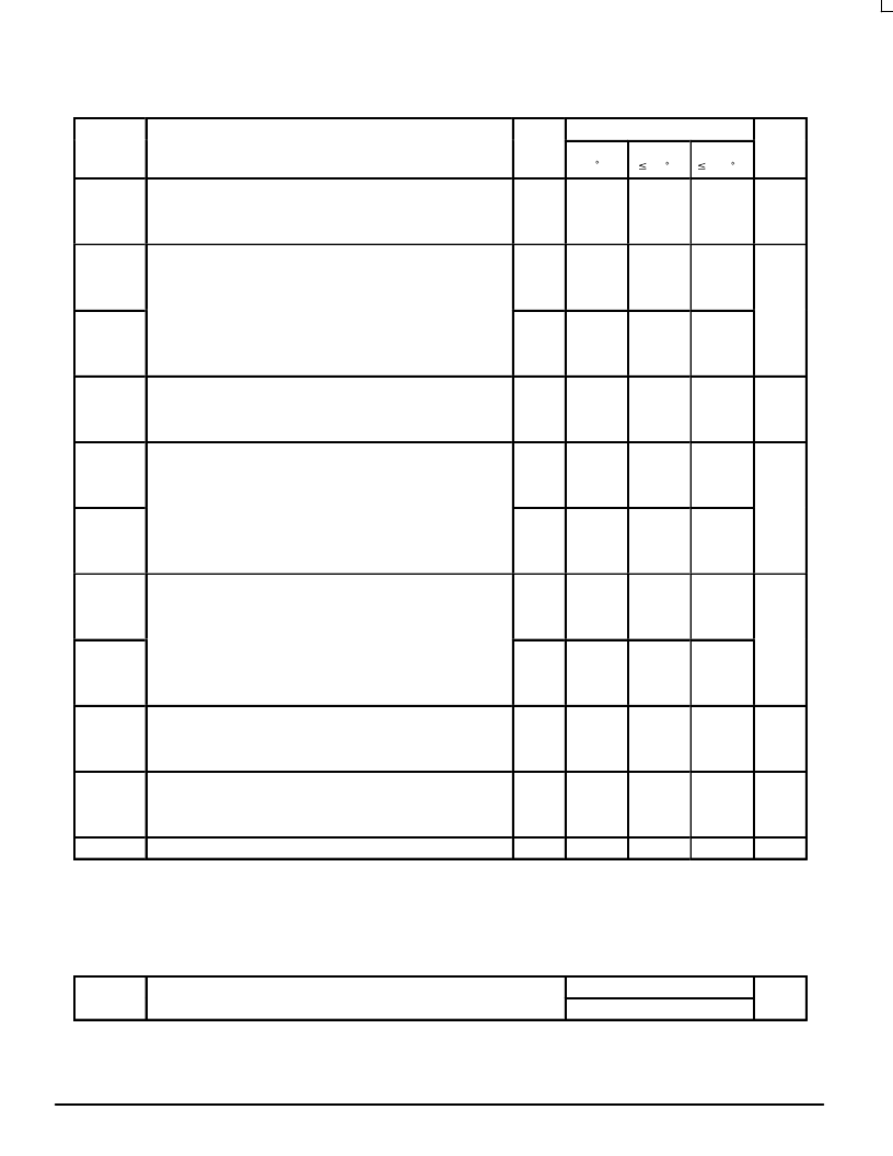
* Applies to noncascaded/nonsynchronously clocked configurations only. With synchronously cascaded counters, (1) Clock to Ripple Carry Out
propagation delays, (2) Enable T or Enable P to Clock setup times, and (3) Clock to Enable T or Enable P hold times determine fmax. However,
if Ripple Carry Out of each stage is tied to the Clock of the next stage (nonsynchronously clocked), the fmax in the table above is applicable.
See Applications Information in this data sheet.
NOTES:
1. For propagation delays with loads other than 50 pF, see Chapter 2 of the Motorola High–Speed CMOS Data Book (DL129/D).
2. Information on typical parametric values can be found in Chapter 2 of the Motorola High–Speed CMOS Data Book (DL129/D).
Symbol
b l
Parameter
25 C
U i
6.0
35
– 55 to
TBD
TBD
29
125 C
24
6.0
(Figures 1 and 7)
3.0
35
43
TBD
28
TBD
6.0
6.0
4.5
6.0
(Figures 1 and 7)
3.0
36
210
TBD
53
54
30
37
TBD
37
TBD
2.0
3.0
27
205
TBD
255
TBD
43
310
TBD
Maximum Propagation Delay, Reset to Q (HC160A Only)
(Figures 2 and 7)
2.0
3.0
43
37
33
265
TBD
45
315
TBD
ns
(Figures 2 and 7)
Maximum Propagation Delay, Enable T to Ripple Carry Out
2.0
6.0
160
175
66
56
200
34
240
41
ns
tPHL
6.0
2.0
6.0
195
245
42
50
295
Maximum Propagation Delay, Clock to Ripple Carry Out
4.5
6.0
2.0
44
37
215
220
220
54
46
265
45
ns
tPHL
2.0
15
270
65
55
325
tPHL
4.5
6.0
Maximum Propagation Delay, Reset to Ripple Carry Out
(HC160A Only)
2.0
22
275
55
47
330
Maximum Output Transition Time, Any Output
19
CPD
Power Dissipation Capacitance (Per Package)*
* Used to determine the no–load dynamic power consumption: PD = CPD VCC2f + ICC VCC. For load considerations, see Chapter 2 of the
Motorola High–Speed CMOS Data Book (DL129/D).
Typical @ 25
°
C, VCC = 5.0 V
60
pF
相關PDF資料 |
PDF描述 |
|---|---|
| MC74HC162AD | Presettable Counters |
| MC74HC162AN | Presettable Counters |
| MC74HC160AD | Presettable Counters |
| MC74HC160AN | Presettable Counters |
| MC74HC160D | Presettable Counters |
相關代理商/技術參數 |
參數描述 |
|---|---|
| MC74HC162DR2 | 制造商:ON Semiconductor 功能描述: |
| MC74HC163AD | 制造商:ON Semiconductor 功能描述:Counter Single 4-Bit Binary UP 16-Pin SOIC Rail 制造商:Rochester Electronics LLC 功能描述:- Bulk |
| MC74HC163ADG | 功能描述:計數器 IC RoHS:否 制造商:NXP Semiconductors 計數器類型:Binary Counters 邏輯系列:74LV 位數:10 計數法: 計數順序: 工作電源電壓:1 V to 5.5 V 工作溫度范圍:- 40 C to + 125 C 封裝 / 箱體:SOT-109 封裝:Reel |
| MC74HC163ADR | 制造商:Rochester Electronics LLC 功能描述: 制造商:ON Semiconductor 功能描述: |
| MC74HC163ADR2 | 制造商:ON Semiconductor 功能描述:Counter Single 4-Bit Binary UP 16-Pin SOIC T/R |
發布緊急采購,3分鐘左右您將得到回復。