- 您現在的位置:買賣IC網 > PDF目錄300047 > TZ03Z050E169B00 High junction temperature Transil PDF資料下載
參數資料
| 型號: | TZ03Z050E169B00 |
| 英文描述: | High junction temperature Transil |
| 中文描述: | 修邊機WASCHFEST國際清算銀行5pF的工業陶瓷1.5PF |
| 文件頁數: | 11/24頁 |
| 文件大小: | 439K |
| 代理商: | TZ03Z050E169B00 |
17
No.T13E4.pdf 99.8.23
This is the PDF file of catalog No.T13E-4.
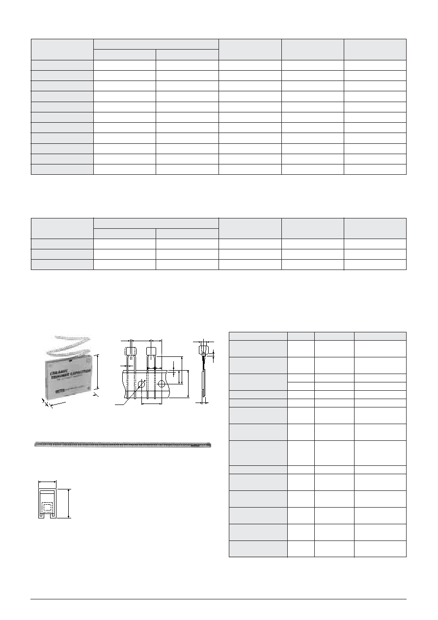
!RATINGS FOR SINGLE PLATE TYPE
!RATING FOR MONOLITHIC PLATE TYPE
!RADIAL TAPING PACKAGE
!MAGAZINE PACKAGE
Part Number
TZ03Z2R3
-169
TZ03Z050
-169
TZ03Z070
-169
TZ03Z100
-169
TZ03N100
-169
TZ03T110
-169
TZ03T200
-169
TZ03R200
-169
TZ03R300
-169
TZ03P450
-169
TZ03P600
-169
Capacitance (pF)
Temperature Coefficient
(ppm/
D)
Q
<1MHz, Cmax.>
Case Color
1.25
1.5
2.0
2.7
2.1
3.0
4.2
5.2
6.8
9.8
2.3
5.0
7.0
10.0
11.0
20.0
30.0
45.0
60.0
NP000
T200
NP000
T200
NP000
T200
NP000
T200
N2000
T200
N4500
T300
N4500
T300
N7500
T300
N7500
T300
N1200
T500
N1200
T500
(0
T200)
(0
T200)
(0
T200)
(0
T200)
(
Y200T200)
(
Y450T300)
(
Y450T300)
(
Y750T300)
(
Y750T300)
(
Y1200T500)
(
Y1200T500)
300 min.
500 min.
300 min.
Black
Blue
White
Pink
Red
Green
Yellow
Brown
Min. (max.)
Max. (
T500%)
Stray capacitance for side adjustment type adapter (YR) is 0.2pF.
Insulation resistance : 104M
min.
Rated voltage : 100Vdc
Withstanding voltage : 220Vdc
Driving Torque : 2.0 to 15.0mNm (Ref.20 to 150gf.cm)
Working Temperature Range :
Y25 to W85D
Part Number
TZ03Z500
-169
TZ03R900
-169
TZ03R121
-169
Capacitance (pF)
Temperature Coefficient
(ppm/
D)
Q
<1MHz, Cmax.>
Case Color
6.0
9.0
10.0
50.0
90.0
120.0
NP00
T300
N750
T300
N750
T300
(0
T300)
(
Y750T300)
(
Y750T300)
300 min.
Orange
Black
WMarking
Black
Min. (max.)
Max. (
T1000%)
Stray capacitance for side adjustment type adapter (YR) is 0.2pF.
Insulation resistance : 104M
min.
Rated voltage : 50Vdc
Withstanding voltage : 110Vdc
Driving Torque : 2.0 to15.0mNm (Ref. 20 to 150gf.cm)
Working Temperature Range :
Y25 to W85D
Part number : TZ03
-OOOTR169T00
Standard packaging : 1,000 pcs. / ammo pack
Flat Pack Outline
Taping Dimensions
Magazine Dimensions
Part number : TZ03
OOOO
-194
- : Terminal style (ER / FR / BR)
Standard packaging : 80pcs./ magazine
508mm long
D0
P0
d
P
F
t
S
h
P1
P2
H
2
H
0
W
1
W
2
330m
ax.
2
7
5
m
a
x
.
40
m
ax
.
1
3
.5
T
0
.4
9.0
T0.3
(in mm)
Item
Pitch of
Component
Pitch of
Sprocket Hole
Length from Hole
Center to Lead
Lead Spacing
Carrier Tape Width
Position of
Sprocket Hole
Hold Down
Tape Position
Lead Distance
between Reference
and Bottom Planes
Stand-off
Diameter of
Sprocket Hole
Total Thickness, Tape
and Lead Wire
Deviation
Across Tape
Deviation Along Tape,
Left or Right
Lead Diameter
Code
P
P0
P1
P2
F
W
W1
W2
H0
H2
D0
t
h
S
d
Dimensions (mm)
12.7
T0.3
3.85
T0.7
6.35
T1.3
5.0
T0.8
0.2
18.0
T0.5
9.0
T0.5
1.5
T1.5
18.0
T0.5
1.3
T0.5
4.0
T0.1
1.7max.
1.5max
0
T1.5
0.6
T0.1 dia.
Remark
Tolerance
with
S
Except 1mm from the
Stand-off Position
!HANDLING PRECAUTIONS / SOLDERING
!CONDITIONS
See pages 20 to 21.
相關PDF資料 |
PDF描述 |
|---|---|
| TZ03Z500E169B00 | High junction temperature Transil |
| TZ03R300E169B00 | High junction temperature Transil |
| TZ150N | High junction temperature Transil |
| TZ150N18KOC | High junction temperature Transil |
| TZ150N18KOF | High junction temperature Transil |
相關代理商/技術參數 |
參數描述 |
|---|---|
| TZ03Z050E169B00 | 制造商:Murata Manufacturing Co Ltd 功能描述:CAPACITOR VARIABLE 1.5 TO 5.0PF |
| TZ03Z050ER169 | 制造商:Murata Manufacturing Co Ltd 功能描述: |
| TZ03Z050F169B00 | 功能描述:整流器/與可變電容器 1.5-5pF 100volt Trimmer Capacitor RoHS:否 制造商:Xicon 電容范圍:2.8 pF to 12.5 pF 容差: 電壓額定值:200 V 工作溫度范圍:- 35 C to + 85 C 端接類型:SMD/SMT 產品:Trimmer Capacitors - Ceramic Dielectric |
| TZ03Z050N169B00 | 功能描述:整流器/與可變電容器 5.0pF 100 volt Trimmer Capacitor RoHS:否 制造商:Xicon 電容范圍:2.8 pF to 12.5 pF 容差: 電壓額定值:200 V 工作溫度范圍:- 35 C to + 85 C 端接類型:SMD/SMT 產品:Trimmer Capacitors - Ceramic Dielectric |
| TZ03Z050T169A00 | 功能描述:整流器/與可變電容器 5.0pF 100 volt Trimmer Capacitor RoHS:否 制造商:Xicon 電容范圍:2.8 pF to 12.5 pF 容差: 電壓額定值:200 V 工作溫度范圍:- 35 C to + 85 C 端接類型:SMD/SMT 產品:Trimmer Capacitors - Ceramic Dielectric |
發布緊急采購,3分鐘左右您將得到回復。